Idea for new shut-off design
First published: 9/2 2013 - Last update: 18/3 2013
|
Here is an idea for a new type of shut-off systems. These shut-offs have not been build and tested yet but here is some images from the CAD program. First a traditional shut-off version to explain the design and function. Next two advanced design that will allow the pilot to stop the engine at will The inspiration for this new shut-off actually came from the magnetic Belarusian shut-off designed by Chapeau Nekhay. I liked the steel ball valve inside the tube. A simple valve submerged in fuel. No sealing's to leak fuel and no pinching of the fuel tube. But the Belarusian shut-off does have a lot of external springs that might be damaged in a hard landing and the moving part is very delicate to oil and sand. To solve these problems the design was turned inside out. Instead of only the small steel ball inside the tube, all moving parts are now inside the tube! AO: A traditional shut-off similar to the Belarusian shut-off PA: Shut-off with Pilot Activation or Stop@Will Split: Shut-off with pilot activation, inspired by the Drop Stop shut-off |
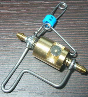 The inspiration for the Ball Maze shut-off came from this Belarusian shut-off |
|
|
Ball Maze Shut-Off - "AO" The first variation of this design is just a classic shut-off. It is named "Ball Maze Shut-Off - AO". (AO is short hand for shut-off in Russian) 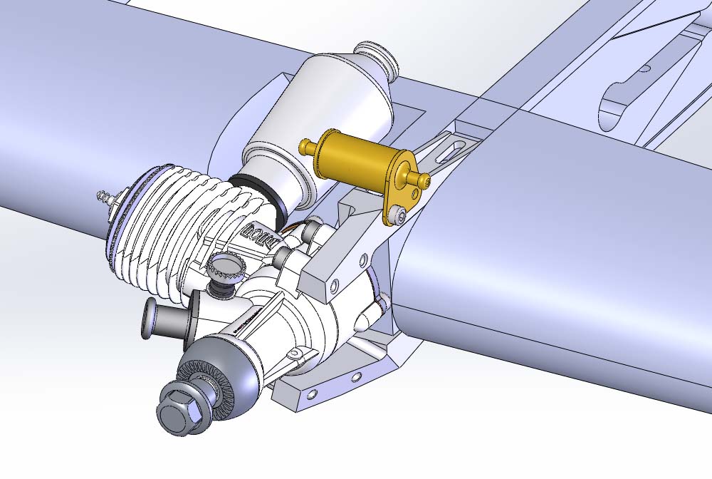 The shut-off system is here shown on a combat model. The fuel from the tank must pass from the outboard side of the shut-off to the tube on the inboard. 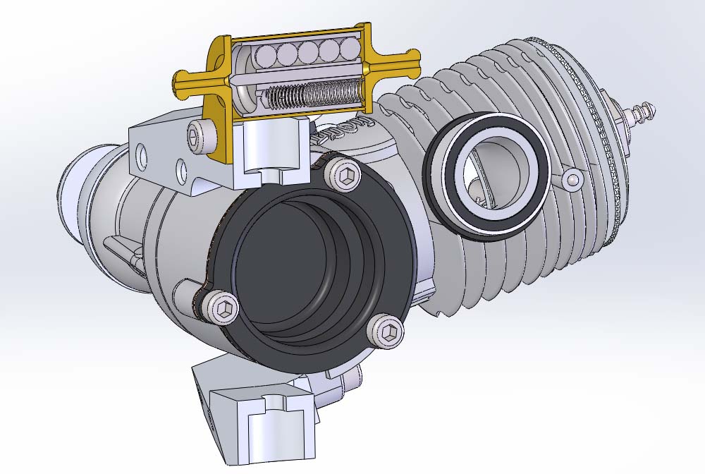 En cut through the shut-off show the internal parts of the device. A needle at the centre of the moving part will act as a valve in the outlet hole when it is forced to the inboard position by the spring. 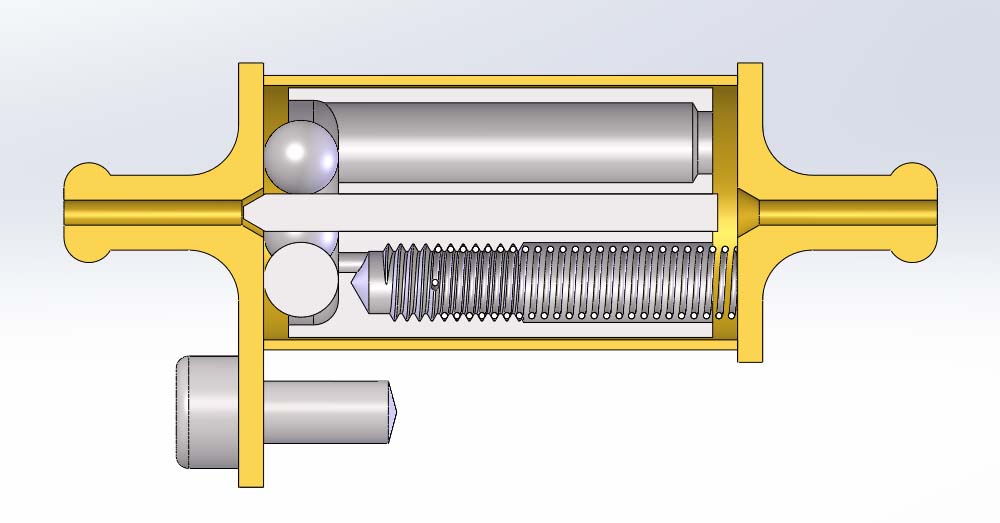 The shut-off is here ready for take-off. Some stainless steel balls between the steel weight and the housing prevent the valve from closing. 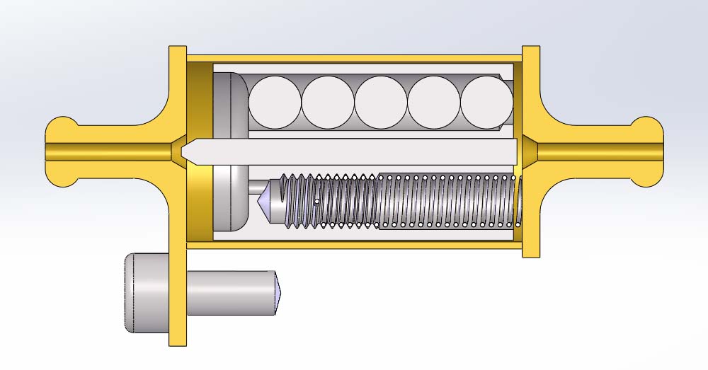 When the model is flying on the lines the weight will move outward. This will set the steel balls free to move around. The steel balls will fall into the hole in the weight. 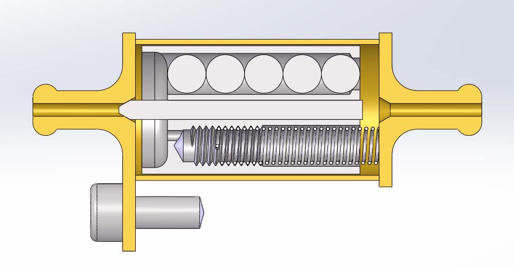 If the model is cut off the lines the spring will push the weight and the needle towards the outlet hole. The steel balls will be in the hole and cannot block the valve from closing off the fuel flow to the engine. 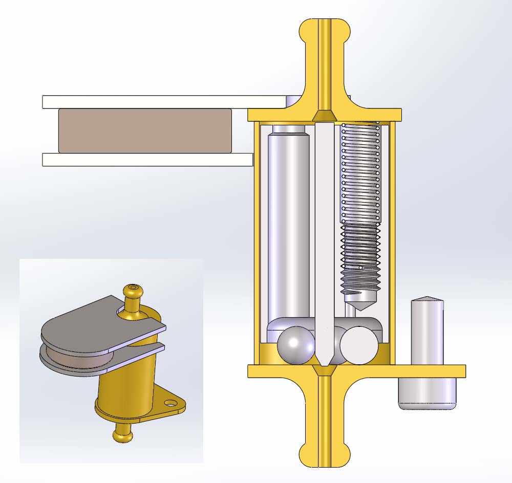 |
||
|
To get the steel balls back in front of the weight the mechanic must hold the model with the inboard tip down and lift the weight with a magnet.
The stainless steel balls are not magnetic and will fall down between the weight and the housing.
When the mechanic removes the magnetic key the spring will push the weight against the steel balls.
The balls are now trapped.
A few may fall down the hole when the mechanic is handling the model but as long as just one ball remain trapped the shut-off stay opened.
All movements of the weight and the steel balls will be damped by the fuel. Any air in the fuel will pass the shut-off. The hole for the spring do even have a small hole at the end to let fuel and air pass through. The spring is formed to fit into the tread at the end of the hole. With a small screwdriver it will be possible to change the position of the spring. This will change the flying speed necessity to keep the shut-off open. The shut-off is adjustable! |
Ball Maze AO cad-files: 3D model (exe-file) 3D model (eDrawing) More info on eDrawings Tech info: Neodymium disc, ø 5 mm x 3 mm from RS Components RS Stock No. 695-0166 Find your local RS Components |
|
|
Ball Maze Shut-Off - "PA" The next variation of the Ball Maze Shut-Off is designed to let the pilot stop the engine at will. It is named "Ball Maze Shut-Off - PA" (PA: Pilot Activated). 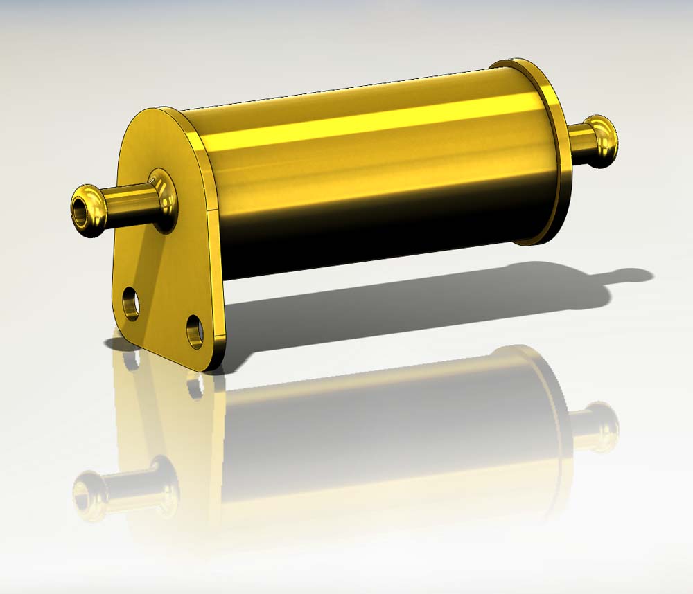
The outside shape is almost the same as the AO shut-off. Just a little bigger. 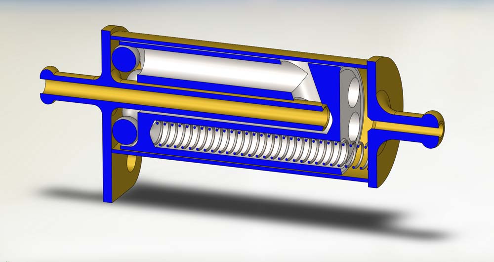
Shut-Off is open and ready for starting the engine. The "valve" is a tube on the fuel outlet that seal against the bottom of the center hole in the weight. 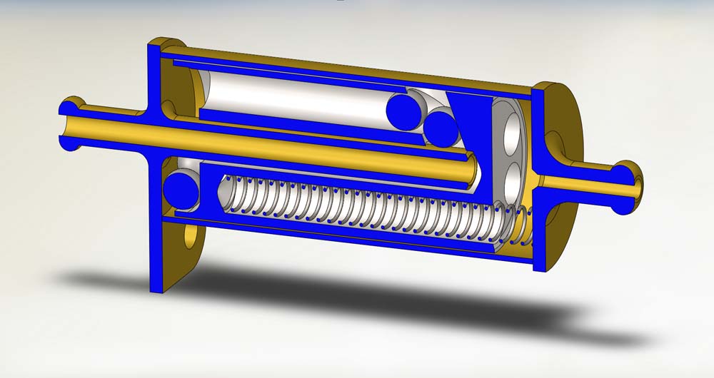
At take-off some of the steel balls may have fallen into the hole but the shut-off is still open. 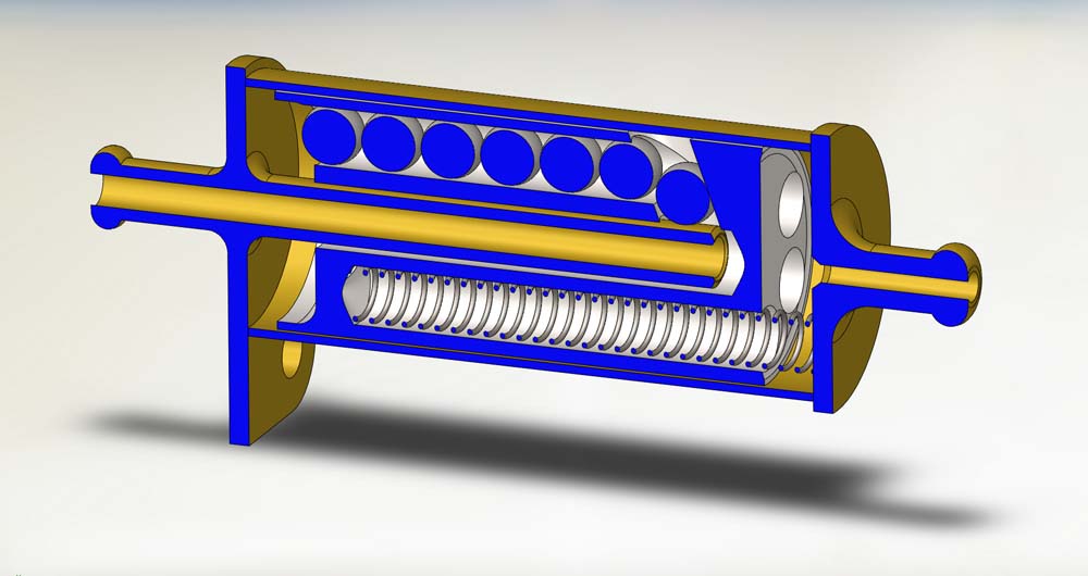
Shortly after take-off all steel balls have found their way down the hole. 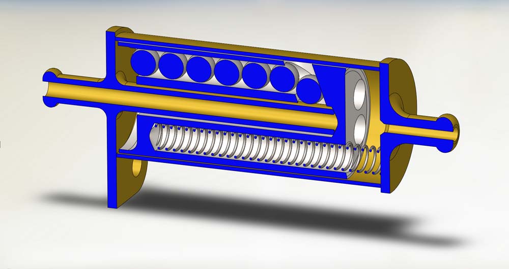
If the model is fly away the shut-off will close and stop the engine. 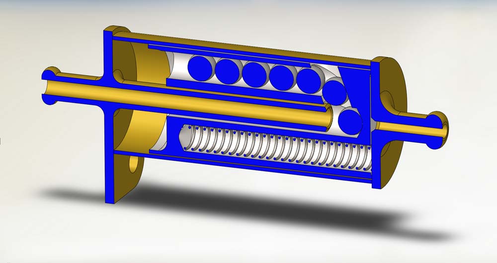
If the pilot gives a hard pull to the lines the centre weight will move to the bottom of the housing. This will allow one of the steel balls to fall into the centre hole. 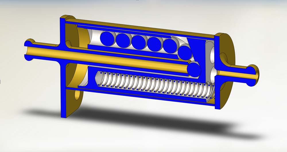
When the weight move back the steel ball in the centre hole will block the fuel and stop the engine. |
||
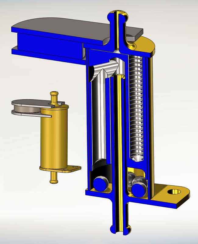
The shut-off can also be reloaded with a magnetic key. |
Ball Maze PA cad-files: 3D model (exe-file) 3D model (eDrawing) More info on eDrawings More info on: Neodymium magnets Data sheet Eclipse Magnetics Ball Maze You probably already know a Ball Maze as a small game where you must try to get one or more balls through a labyrinth (or maze) and into a hole. It is also known as a Ball-in-a-maze puzzle Images of Ball Maze Ball Maze Split cad-files: 3D model (exe-file) 3D model (eDrawing) |
|
|
Ball Maze Shut-Off - "Split" Another design for a pilot activation is the "Ball Maze Shut-Off - Split" 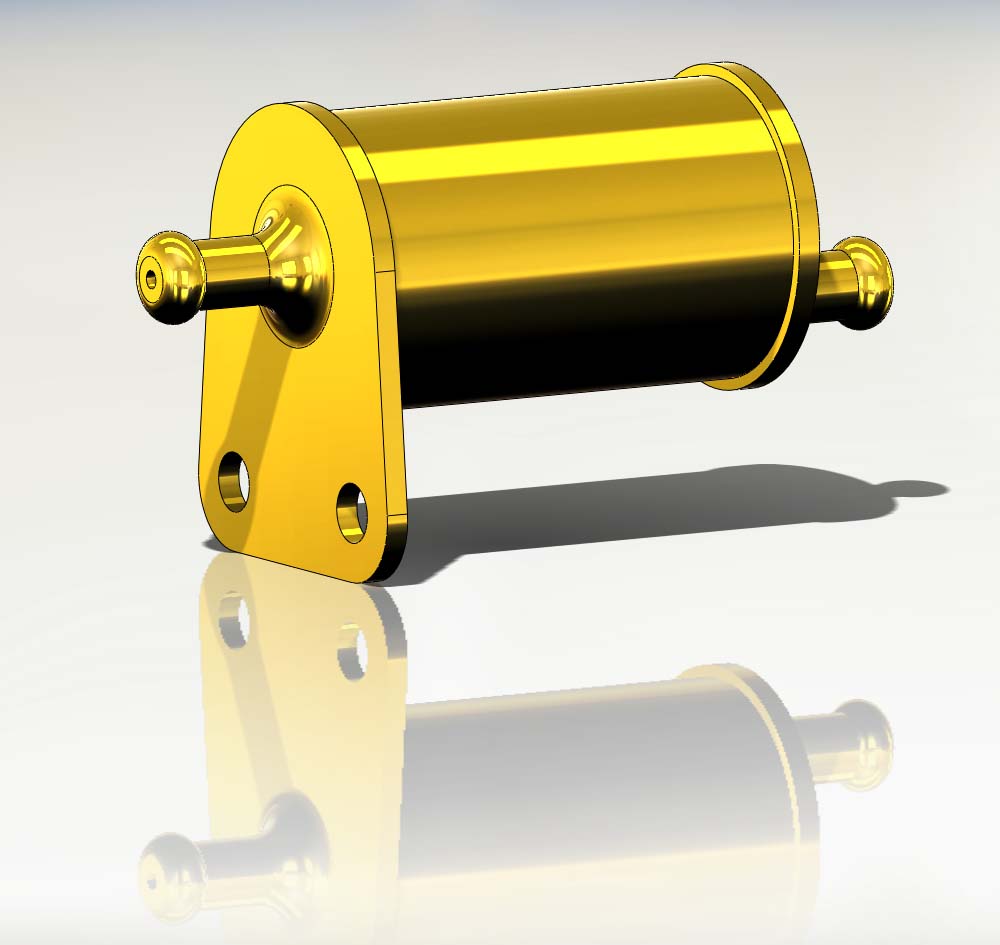
The centre weight is here separate into two parts. The springs are acting on the part with the valve and the other part is connected with a strong magnet. In principal the same idea as used for the Drop Stop shut-off If the pilot pulls the lines the two parts separate. When the moving weight has lost most of its mass the spring will push it back and close the valve. 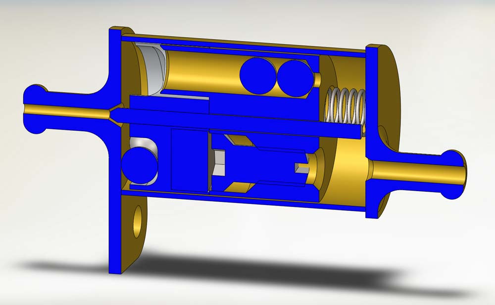
A cut through the shut-off. 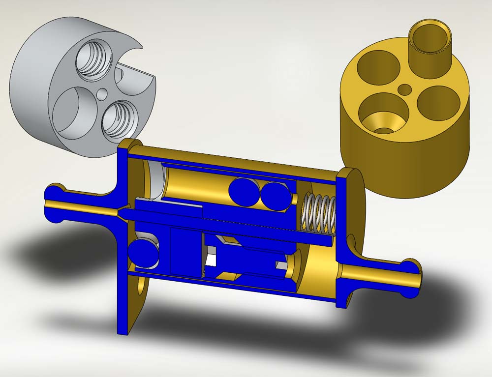
The position of the spring can be adjusted to give make the shut-off stop the engine if the model is flying away. 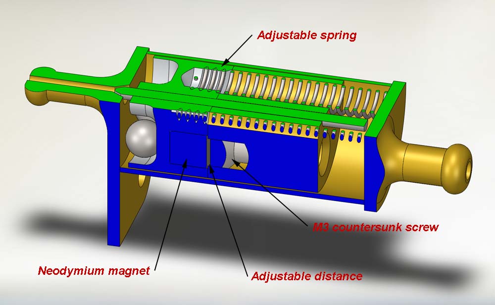
The distance between the magnet and the head of the countersunk screw set the force it takes to separate the two parts. By adjusting the position of the screw the pilot can adjust how hard he must pull the lines to stop his engine. 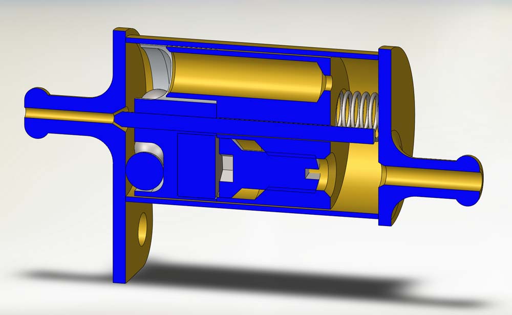
The shut-off ready for take-off 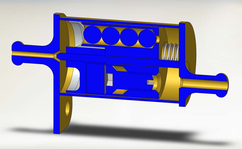
The shut-off at normal flight. 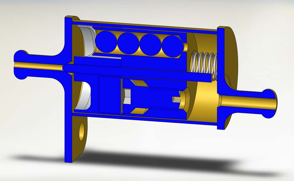
Fly-away. The shut-off stop the fuel supply to the engine. 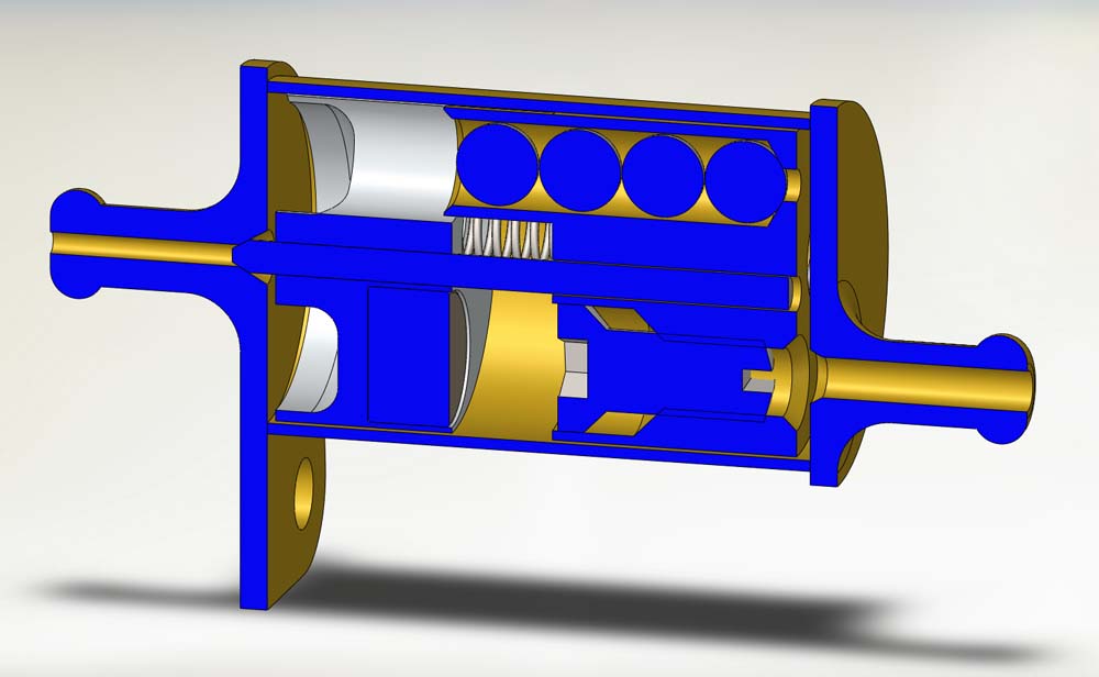
Pilot activated stop. The moving weight has been separated by a hard pull on the lines. After landing the free part of the weight will automatically reattach to the other part of the weight. |
||
|
|
||
|
Permalink: https://www.f2d.dk/stopatwill/ballmaze.htm - Public domain - Spell checking doc |
||